They connect only to the power and ground rails once power rails are created in the design. To participate you need to register.
![]()
Lung Dap Identity By Design For Healthcare Via Behance Lunges Charity Logos Graphic Design Logo
End Cap Cells VLSI Physical Design Tuesday 20 October 2015 End Cap Cells These library cells do not have signal connectivity.

. End-cap cells are preplaced physical-only cells required to meet certaindesign rules and placed at the ends of the site rows by satisfying well tie-off requirements for the core rows These library cells do not have any signal connectivity They connect only to the power and ground rails once power rails are created in the design. END cap cells are used for N WELL continuity and also main reason is characterization team will create a library for a cell is adjoin with other cells. We cant have functional failure in our design.
DeCap Cells in Physical Design Use of Decap Cells in PD. We have explained all about end cap cells in this session with the he. Current I Increases near inductor so L d Id t increases due to which Voltage.
These cells prevent the cell damage during fabrication. Before starting the actual placement of the standard cells present in the synthesized netlist we need to place various physical only cells like end-cap cells well-tap cells IO buffers antenna diodes and spare cells. So Well-taps cells are added in partitionchip level to tie the wells to VDDVSS.
Their layout is different from that of a filler or Dcap 2. This prevents DRC violations by satisfying well tie-off requirements for the core rows. Boundary cells does exact opposite of it.
These cells essentially act as a capacitance between power and ground rails and hence as a charge reservoir that can be counted upon while there is a high demand for current from the power lines. Decap Cells Decoupling capacitors are another type of physical only cells used in PD flow. It breaks the n-well in a way avoiding any DRCs.
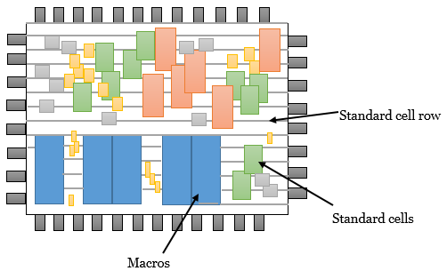
These are used to address boundary N-Well issues for DRC cleanup. A typical view after preplacement has shown in figure-1. These library cells do not have any signal connectivity.
Filler Cells Once you have completed placement and routing there are usually gaps left in the layout where you do not have any standard cells present. It is not possible to abut every cell available as that would cause. End cap cells are also known as boundary cells.
Tie Cell insertion 10. Filler type of physical only cells are used to ensure continuity between well or implant layers that would not cause design rule violations. These library cells do not have signal connectivity.
The library cells do not have cell connectivity as they are only connected to power and ground rails thus to ensure that gaps do not occur between well and implant layer and to prevent the DRC violations by satisfying well tie-off requirements for core rows we use end-cap cells. Click here to register now. VLSI PHYSICAL DESIGN FOR FRESHER will be helpful for the Physical design engineer and to find physical design engineer jobs.
What is end cap cell or Boundary cell What is the use of end cap cells in ASIC Design. Decap cell is basically a capacitor cell which is used temporarily in the design between power and ground rails to counter the functional failure. They connect only to the power and ground rails once power rails are created in the design.
A filler or Dcap cells actually helps in continuity of n-well. To avoid drain and source short. This is a physical-only cell.
IO cell pad cell Libraries. End Cap Cells. Used for row connectivity and specifying row ending.
We cant have functional failure in our design. It is used to isolate several designs and IPs in a SOC. Why do we add Row-End Cap cells in our flow.
So to avoid any kind of functional failure due to Dynamic IR we use Decap cells in our design. VLSI- Physical Design For Freshers. Each end of the core row left and right can have only one end cap cell specified.
There are various reasons for the instant large current requirement in the circuit and if there are no adequate measures have taken to handle this requirement power. End cap cells are pre placed physical only cells it has only physical connectivity. End cap Cells.
Fig1 End-cap cells are typically nonlogic cells such as a decoupling capacitor for the power rail. EndCap Cells These cells are inserted to take care of boundary DRC of Wells Other layers. Boundary cells consist of end-cap cells which are added to the ends of the cell rows and around the boundaries of objects such as the core area hard macros blockages and voltage areas and corner cells which fill the empty space between horizontal and vertical end-cap cells.
End cap cells YOUR DESCRIPTION HERE. End-cap cell are physical only cells which are added to identify end of rows in digital chips or blocksThey are also added to isolate any analog IPs and digital part of any chips. Filler Cells Well Tap Cells Decap Cells.
These do not have any logical functionality. If we are not place these cells at the end of rows the row end cell of any combo or FF cells may not surrounded the another cells it may cause. End Cap Cells ensure proper terminations of rows so that no DRC are created.
Decap cells are basically a charge storing device made of the capacitors and used to support the instant current requirement in the power delivery network. End-cap cells are preplaced physical-only cells required to meet certaindesign rules and placed at the ends of the site rows by satisfying well tie-off requirements for the core rows. They connect only to the power and ground rails once power rails are created in the design.
Forum focused on EDA software circuits schematics books theory papers asic pld 8051 DSP Network RF Analog Design PCB Service Manuals. Tap-gate spacing has to be met while adding well-tap array. However you can specify a list of different end caps for inserting horizontal.
End cap cells in Physical design - Free download as PDF File pdf Text File txt or read online for free. Let us continue with the physical only cells present in the standard cell libraries that ease the digital PD flow. And a whole lot more.
They also ensure that gaps do not occur between the well and implant layers. So thats the reason we are giving END cap cells at the ROW end.

Standard Cell Library Digital Design Analog Design Turnkey Asic Soc Embedded Firmware
Wood Framing Double Top Cap Framing Construction Floor Framing Porch Design
2

Conjugation F Plasmid Transfer Microbiology Chemistry Biology

Team Vlsi Decap Cells In Physical Design Use Of Decap Cells In Pd

Silva Cells In Del Mar California Underground Bioretention Case Study Deeproot Blog Improvement Projects Floor Plans Del Mar
Placement Vlsi Physical Design For Freshers

Pin On Mitzvah Planning
0 comments
Post a Comment